Equipment
Here follows the list of additional equipment available for the Hackathon:
LattePanda starter sensor kit
This kit contains 14 among sensors, switches and LEDs.
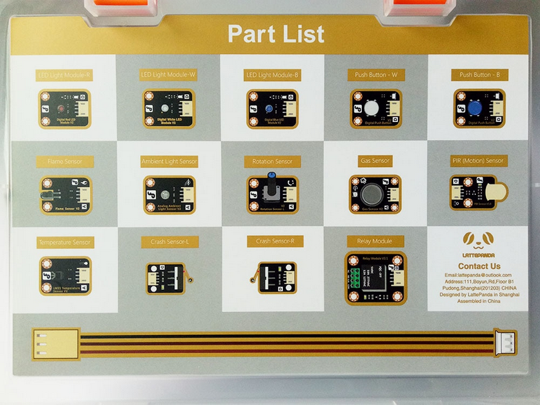
Please, refer to the hyper-links for more details on each single component.
- x1 PIR (Motion) Sensor
- x1 Analog Gas Sensor(MQ2)
- x1 Analog Flame Sensor
- x1 Analog LM35 Temperature Sensor
- x1 Analog Ambient Light Sensor
- x1 Crash sensor(Left)
- x1 Crash sensor(Right)
- x2 Digital Push Button)
- x1 Analog Rotation Sensor V2
- x3 Digital LED Light Module
- x1 Relay Module V3.1
- x14 Gravity Sensor cable
Here below, the piece of code you can use to play with the PIR (Motion) sensor:
Pycom script
The sensor pins +, - and D should be connected to the VIN, GND and G4 pins of the Expansion board, respectively.
import os
import time
import machine
from machine import Pin

uart = machine.UART(0, 115200)
os.dupterm(uart)
pir = Pin('G4',mode=Pin.IN, pull=Pin.PULL_UP)

while True:
    if pir() == 1:
        print("Somebody is in this area!")
    else:
        print("No one!")
    time.sleep_ms(500)
Seeeduino script
The sensor pins +, - and D should be connected to the 5V, GND and 2 pins of the Seeeduino board, respectively.
byte sensor = 2;
byte indicator = 13;

void setup() {
  SerialUSB.begin(115200);
  while(!SerialUSB);
  pinMode(sensor,INPUT);
  pinMode(indicator,OUTPUT);
}

void loop() {
  byte state = digitalRead(sensor);
  digitalWrite(indicator,state);
  if(state == 1)SerialUSB.println("Somebody is in this area!");
  else if(state == 0)SerialUSB.println("No one!");
  delay(500);
}
ELEGOO sensor modules Kit V2.0
The set consists of 37 sensor modules and a small resistor bag.
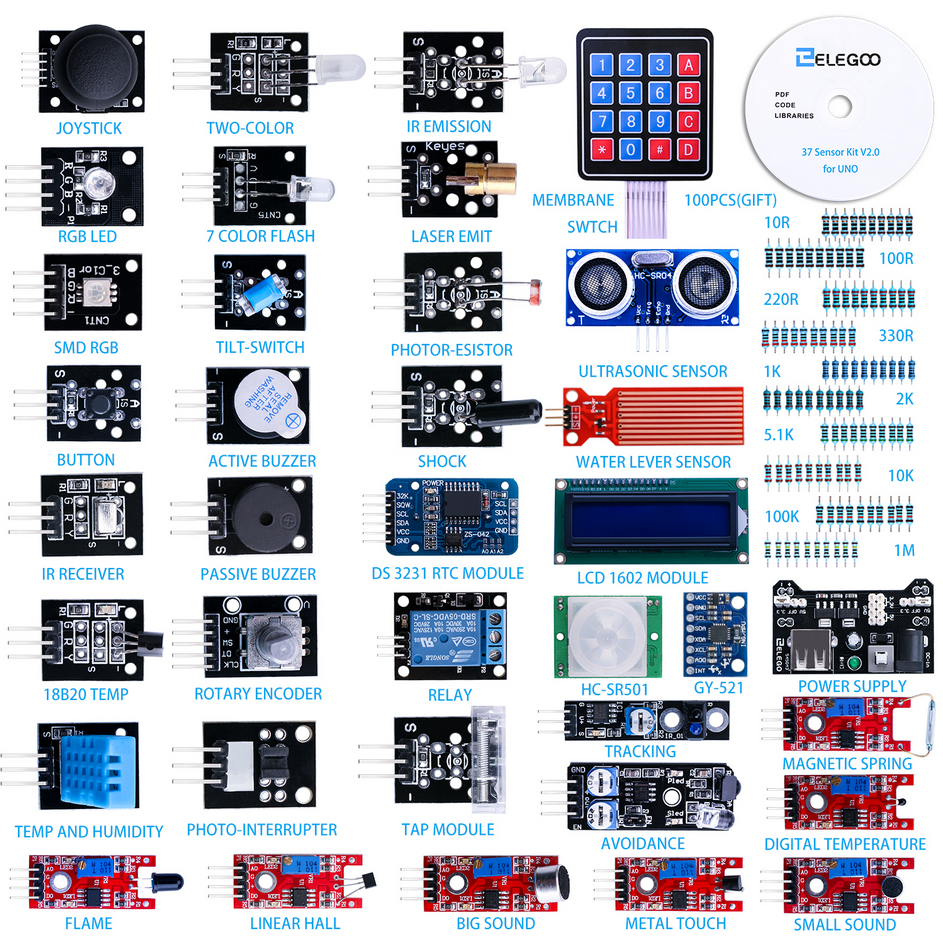
Please, look at this repository to find the datasheet and a sample script (C) for each sensor. As an example, here is the script to read from the temperature sensor.
Seeeduino script
Here below, an example on how to manage the sound sensor with Seeeduino. Pay attention to connect the A0, G, +, and D0 pins of the sensor to the A0, GND, 5V and 7 pins of the Seeeduino board, respectively.
int  sensorAnalogPin = A0;    // Select the Arduino input pin to accept the Sound Sensor's analog output
int  sensorDigitalPin = 7;    // Select the Arduino input pin to accept the Sound Sensor's digital output
int  analogValue = 0;         // Define variable to store the analog value coming from the Sound Sensor
int  digitalValue;            // Define variable to store the digital value coming from the Sound Sensor
int  Led13 = 13;              // Define LED port; this is the LED built in to the Arduino (labled L)

void setup()
{
  Serial.begin(9600);
  pinMode(sensorDigitalPin,INPUT);
  pinMode(Led13,OUTPUT);
}

void loop(){
  analogValue = analogRead(sensorAnalogPin);
  digitalValue=digitalRead(sensorDigitalPin);
  SerialUSB.println(analogValue);

  if(digitalValue==HIGH)      // When the Sound Sensor sends signal, via voltage present, light LED13 (L)
  {
    digitalWrite(Led13,HIGH);
  }
  else
  {
    digitalWrite(Led13,LOW);
  }

  delay(50);                  // Slight pause so that we don't overwhelm the serial interface
}
If you're more likely to use python, that's the code to make it working with Pycom.
Pycom script
In this case, make sure to have connected A0, G, +, and D0 pins of the sensor to the G5, GND, 3V3 and G4 pins of the Pycom board, respectively.
import os
import time
import pycom
import machine
from machine import Pin
from machine import ADC

pycom.heartbeat(False)

uart = machine.UART(1, 9600)
sensorDigitalPin= Pin('G4',mode=Pin.IN, pull=Pin.PULL_UP)
adc = ADC(0)
sensorAnalogPin = adc.channel(pin='P13', attn=ADC.ATTN_11DB) # Be carefull not to plug a voltage bias higher than 1V into the Pycom pins. Here we set a 11dB attenuation as the analog autput from the sound sensor is in the range 0 to 5V.

while True:
    print(sensorAnalogPin.value())
    if sensorDigitalPin()==1:
        pycom.rgbled(0x000033)
    else:
        pycom.rgbled(0x000000)
    time.sleep_ms(50)

This work is licensed under a Creative Commons Attribution 4.0 International License.